Fall Detection System
Short Summary
Falls are a major health risk, especially for patients in rehabilitation or senior care. Our Fall Detection System (FDS) is a lightweight, wearable pendant that uses embedded sensors and microcontroller-based processing to detect falls in real time and notify caregivers—without storing sensitive user data.
Problem
Each year, hundreds of thousands of people die from falls worldwide. In rehabilitation centers, patients recovering from trauma may fear falling due to the lack of immediate assistance. Current solutions either compromise privacy, are overly sensitive, or rely on expensive infrastructure.
Solution
The FDS pendant leverages:
- BNO055 9-axis IMU (accelerometer + gyroscope + magnetometer)
- ATmega328 microcontroller for processing
- HM-11 Bluetooth module for wireless alerts
It detects falls using an on-device, rule-based algorithm and triggers alerts to a dedicated Android application, ensuring rapid caregiver response.
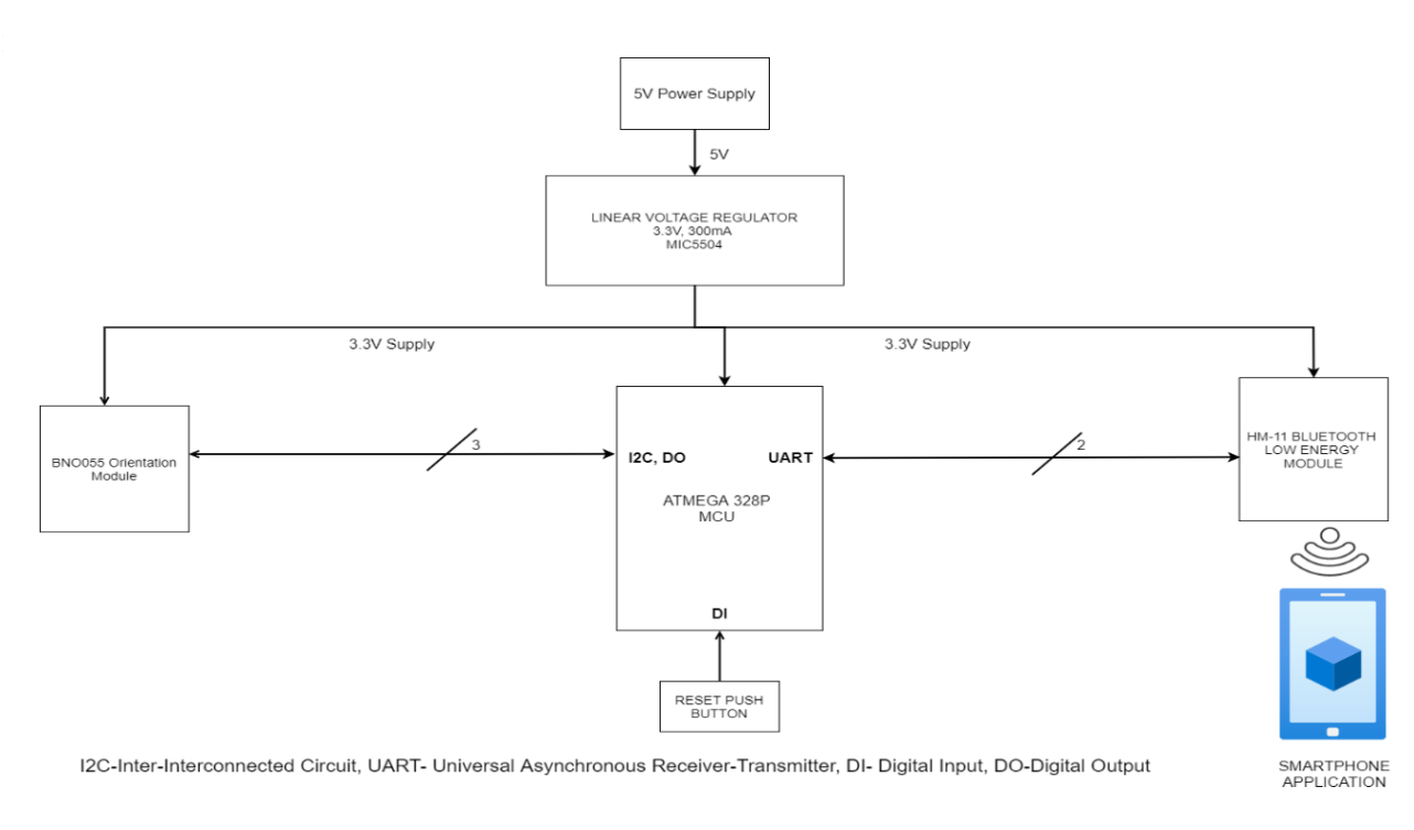
Hardware Block Diagram
How It Works
Data Collection
The IMU continuously outputs 3-axis orientation and acceleration data over I2C.
On-Device Processing
The ATmega328 reads the sensor data, applies threshold-based rules, and determines if a fall has occurred.
Edge Communication
Fall events are transmitted via BLE to the Android app, which displays the patient’s status and sends notifications if needed.
Notification & Safety
Local LEDs indicate device status; fall alerts trigger app notifications to caregivers. Data remains on-device for privacy.
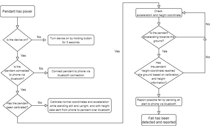
Software Methodology Flowchart
Key Features
- Low-power, wearable hardware
- Real-time fall detection with configurable thresholds
- On-device processing ensures privacy
- BLE-based notifications to caregivers
- Simple Android interface for monitoring patient status
- Modular design: LEDs, switches, and battery charging integrated
Hardware & Software Stack
Hardware
- IMU: BNO055 (accelerometer + gyroscope + sensor fusion)
- Microcontroller: ATmega328 8-bit AVR
- Wireless: HM-11 BLE module
- Power: 3.7V Li-Ion battery, MCP73832 charger, MIC5504-3.3 voltage regulator
- Indicators: LEDs for charging and device status, tactile switches for calibration and reset
Software
- Firmware: C++ (MPLAB)
- Android App: Android app with TinyDB for data storage
PCB & Hardware Design
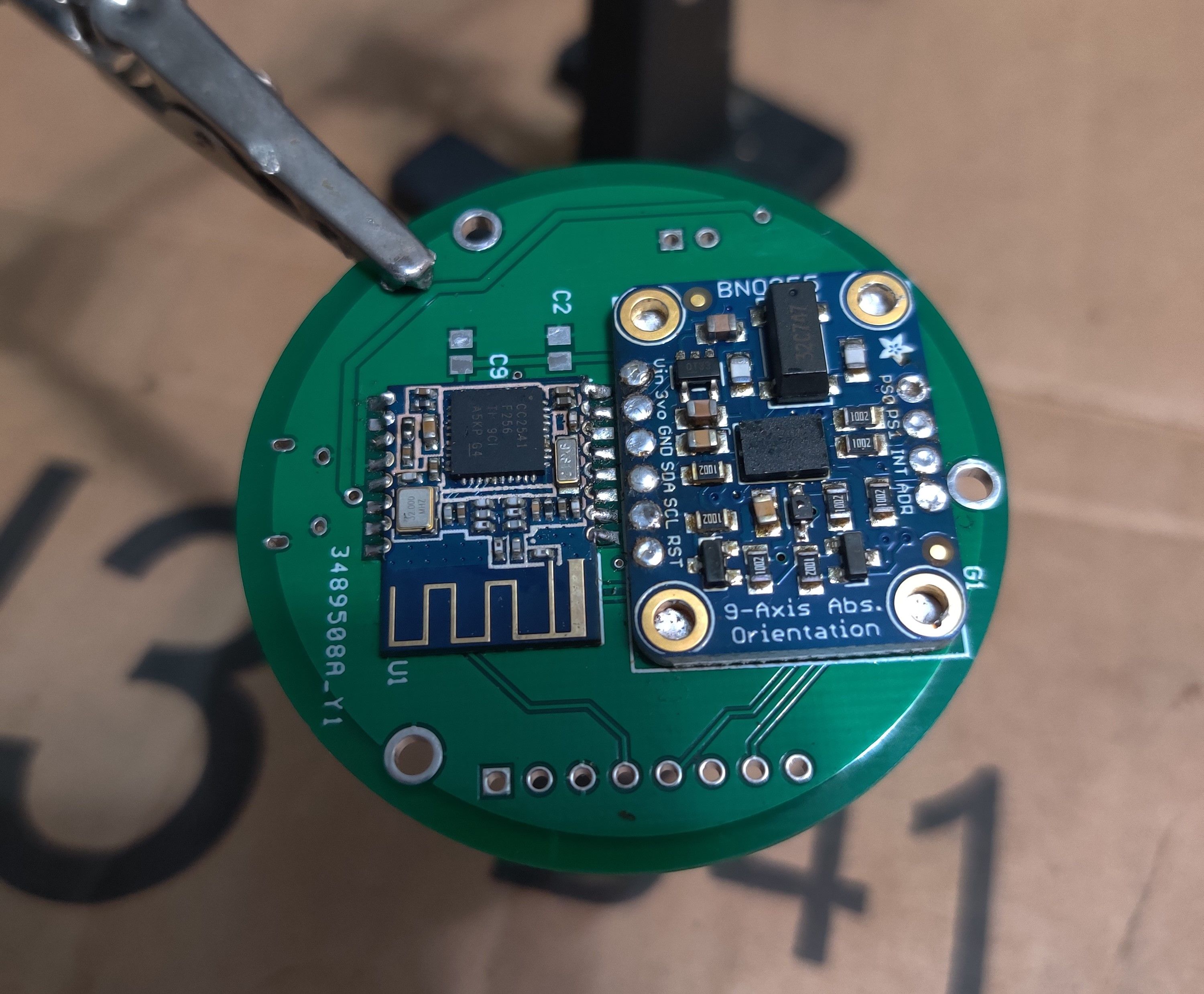
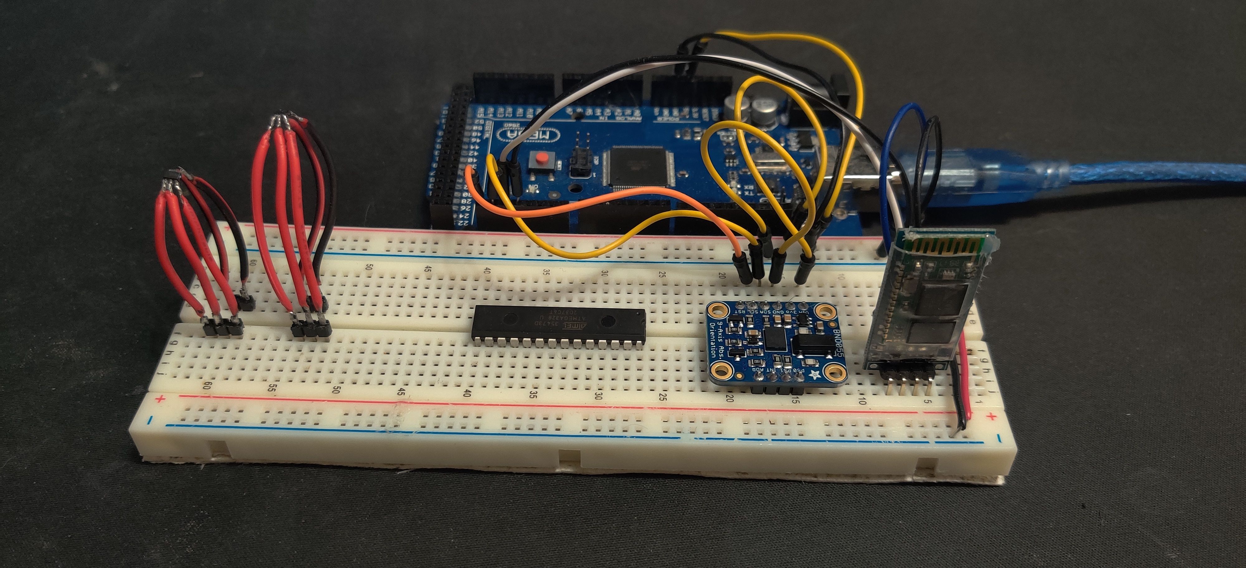
The FDS prototype is built on a custom PCB that integrates all components compactly for pendant use:
- IMU Placement: The BNO055 is positioned centrally for accurate orientation measurement.
- Microcontroller: ATmega328 placed for efficient routing of I2C and UART connections.
- BLE Module: HM-11 located near PCB edge to optimize antenna performance.
- Power Circuit: Li-Ion battery and MCP73832 charger integrated with MIC5504 voltage regulator for stable 3.3V output.
- Indicators & Switches: LEDs for status and charging, tactile switches for reset and calibration, debounced via RC low-pass filtering.
- PCB Layout: Carefully routed traces and bypass capacitors ensure minimal noise and stable operation.
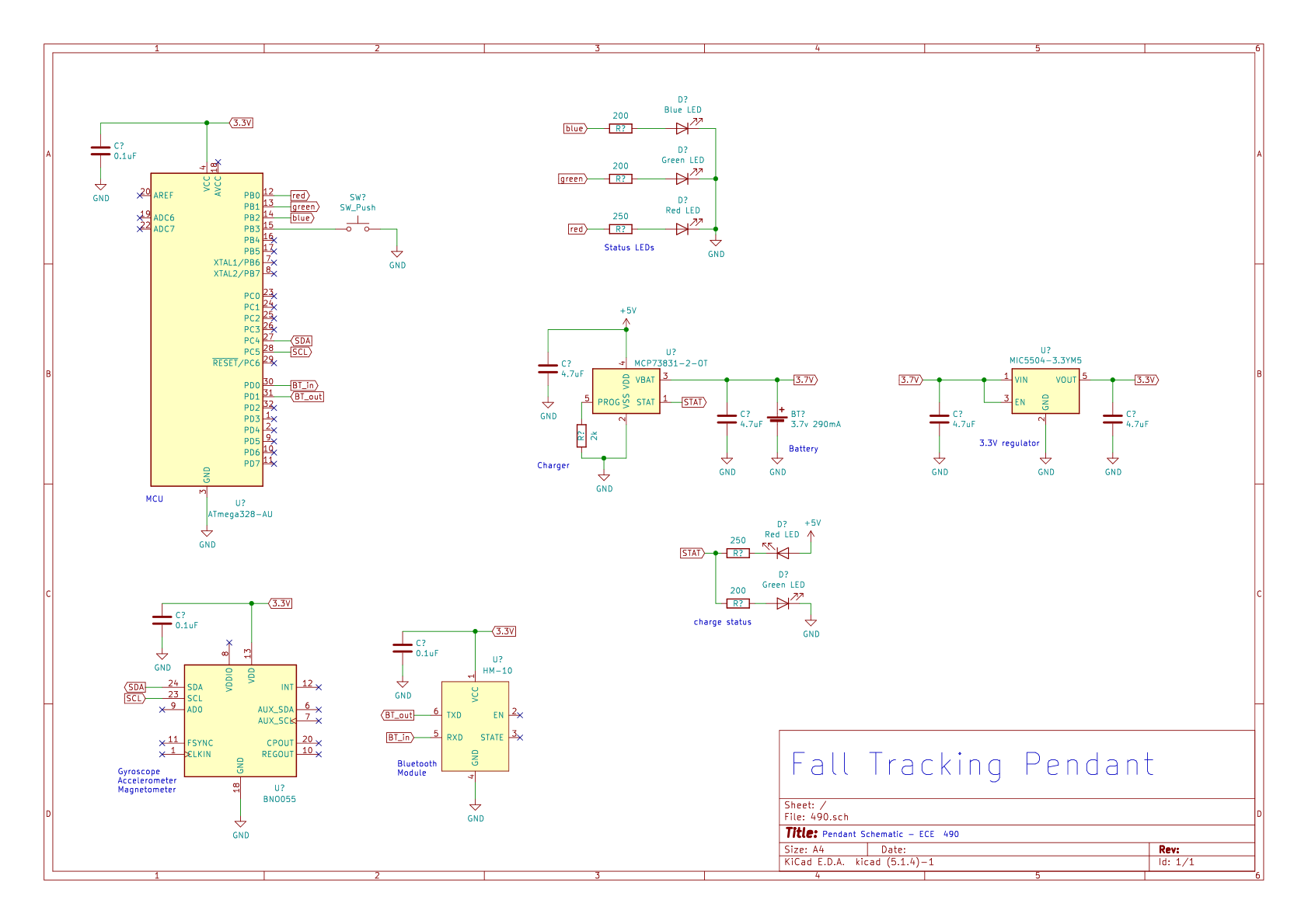
Schematics & PCB Images
Evaluation & Testing
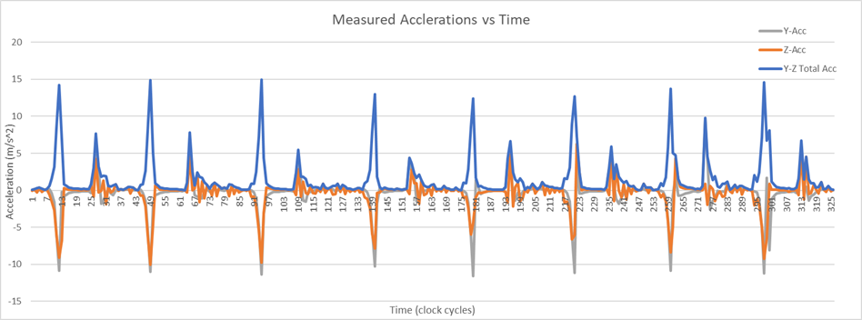
- Multiple drop tests simulated real-world falls, producing peaks in acceleration data for calibration.
- The system accurately differentiates between normal activities (walking, standing) and falls.
- Minimal latency ensures rapid caregiver intervention.
Collected Data
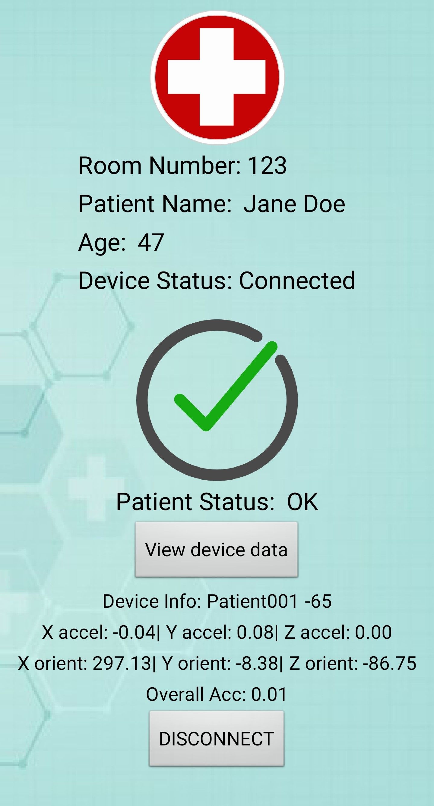
Android App UI
- Displays patient status
- Allows caregivers to acknowledge falls and track patient activity
Conclusion
The FDS pendant demonstrates a practical, low-cost embedded solution for real-time fall detection. With IMU sensors, microcontroller processing, BLE communication, and Android monitoring, the system is ideal for rehabilitation centers, senior care, and any environment where patient safety and privacy matter. Future improvements will focus on reducing latency and supporting multiple devices simultaneously.
Check Out The Full Report
For a detailed breakdown of the hardware design, software methodology, schematics, and test results, check out the PDF below.